A switch, left alone, floods a broadcast frame out every port: every device plugged into it shares one broadcast domain. That is fine for a closet of ten machines and a problem for a building of a thousand, where the broadcast chatter alone becomes a tax and where finance, guest Wi-Fi, and IP phones have no business seeing each other’s frames. The old fix was more switches and more cable, one physical network per group. VLANs do it in software: they carve one physical switch fabric into many logically separate networks that never touch, without laying a second strand of copper.
The idea
A VLAN is a broadcast domain partitioned and isolated at the data link layer (OSI layer 2). Switches keep frames from different VLANs apart by tagging each frame with a 12-bit VLAN ID inside an 802.1Q header. A switch will not bridge traffic between VLANs, so crossing from one to another requires a router, exactly as if they were separate physical LANs.
Segmentation without separate cable
A VLAN behaves like a virtual switch that shares the same physical structure with other VLANs while staying logically separate. It works by applying tags to frames forwarded within the broadcast domain, creating the appearance of traffic split across separate networks even though one set of cabling and switches carries all of it. Because switches do not bridge between VLANs, each VLAN is its own broadcast domain, and breaking a large network into smaller ones reduces the broadcast load every device has to absorb. A VLAN usually maps one-to-one to an IP subnet, so the segmentation you see in subnetting at layer 3 lines up with the VLAN boundary at layer 2. Getting a packet from one VLAN to another means routing between the subnets, which is where a router (or a layer-3 switch) filters broadcasts and enforces policy between the segments.
The 802.1Q tag: 32 bits between MAC and EtherType
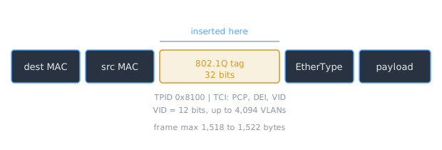
The near-universal way to carry VLAN membership is IEEE 802.1Q, often called Dot1q, which defines VLAN tagging for Ethernet frames. It adds a 32-bit field between the source MAC address and the EtherType field of the original frame, which pushes the maximum frame size from 1,518 to 1,522 bytes. Two of those bytes are the tag protocol identifier (TPID), set to 0x8100 and sitting where the EtherType would be so a receiver can tell a tagged frame from an untagged one. The other two bytes are tag control information, and inside them is the field that does the real work: the VLAN identifier (VID), a 12-bit number specifying the VLAN the frame belongs to. Values 0 and 4095 are reserved, leaving up to 4,094 usable VLANs. The MAC addresses are untouched; the tag rides between the source MAC and the type field the switch was already reading.
Access ports, trunks, and the native VLAN
How a port treats tags depends on its role. An access port faces an ordinary end device (a laptop, a printer, a phone) that knows nothing about VLANs. The device sends plain untagged frames; the switch tags them with the access port’s VLAN on the way in and strips the tag on the way out. The endpoint never sees 802.1Q at all.
A trunk port connects two switches (or a switch to a router or hypervisor) and carries many VLANs over one link. Here the tag stays on, because the far end needs to know which VLAN each frame belongs to. Simpler equipment can only partition per physical port, so each VLAN would need its own cable; tagging is what lets a single interconnect, the trunk, transport data for multiple VLANs at once.
The exception is the native VLAN. On a trunk, one VLAN is designated native and its frames cross the trunk untagged. The rule that makes this work is in the standard: a frame in the VLAN-aware part of the network that does not contain a VLAN tag is assumed to be flowing on the native VLAN. That backward-compatible convenience is also a classic footgun, because a mismatch in the native VLAN between two ends of a trunk, or an injected extra tag, is the basis of VLAN-hopping attacks (see LAN-layer attacks).
One frame, two ports
A laptop on VLAN 20 sends a normal untagged frame into its access port. The switch stamps VID 20 into an 802.1Q tag and forwards it. When the frame needs to reach a second switch, it leaves over the trunk still carrying VID 20, so the second switch knows to keep it inside VLAN 20 and never leaks it to VLAN 10. Reaching the far switch’s access port for the destination, the tag is stripped and a plain frame is delivered. The endpoints on both ends only ever saw untagged Ethernet.
Isolation is a switch promise, not encryption
VLAN separation is enforced by switch forwarding rules, not cryptography. Frames on different VLANs share the same wire and hardware, so the isolation holds only as long as the switch configuration and trunk boundaries are correct. VLANs are a segmentation and management tool; they are not a substitute for firewalls or link encryption.
Related Notes
- ARP and MAC Addressing - the layer-2 addressing the 802.1Q tag sits beside
- IP Addressing and Subnetting - the layer-3 subnets VLANs usually map onto
- OSI and TCP/IP Models - the data link layer where VLANs live
- MTU and Fragmentation - why the extra tag bytes matter to frame size
- ARP Spoofing and LAN Attacks - VLAN hopping and other layer-2 abuses
Sources
- “Virtual LAN,” Wikipedia. https://en.wikipedia.org/wiki/VLAN . Backs a VLAN being a broadcast domain partitioned and isolated at the data link layer, VLANs working by tagging frames, switches not bridging between VLANs, per-port partitioning versus trunk tagging that lets one interconnect carry multiple VLANs, and 802.1Q being the most common protocol.
- “IEEE 802.1Q,” Wikipedia. https://en.wikipedia.org/wiki/IEEE_802.1Q . Backs 802.1Q (Dot1q) defining VLAN tagging for Ethernet, adding a 32-bit field between the source MAC and EtherType, the frame size going from 1,518 to 1,522 bytes, the 0x8100 TPID, the 12-bit VID with 0 and 4095 reserved and up to 4,094 VLANs, and untagged frames in a VLAN-aware network being assumed to flow on the native VLAN.